So you got a
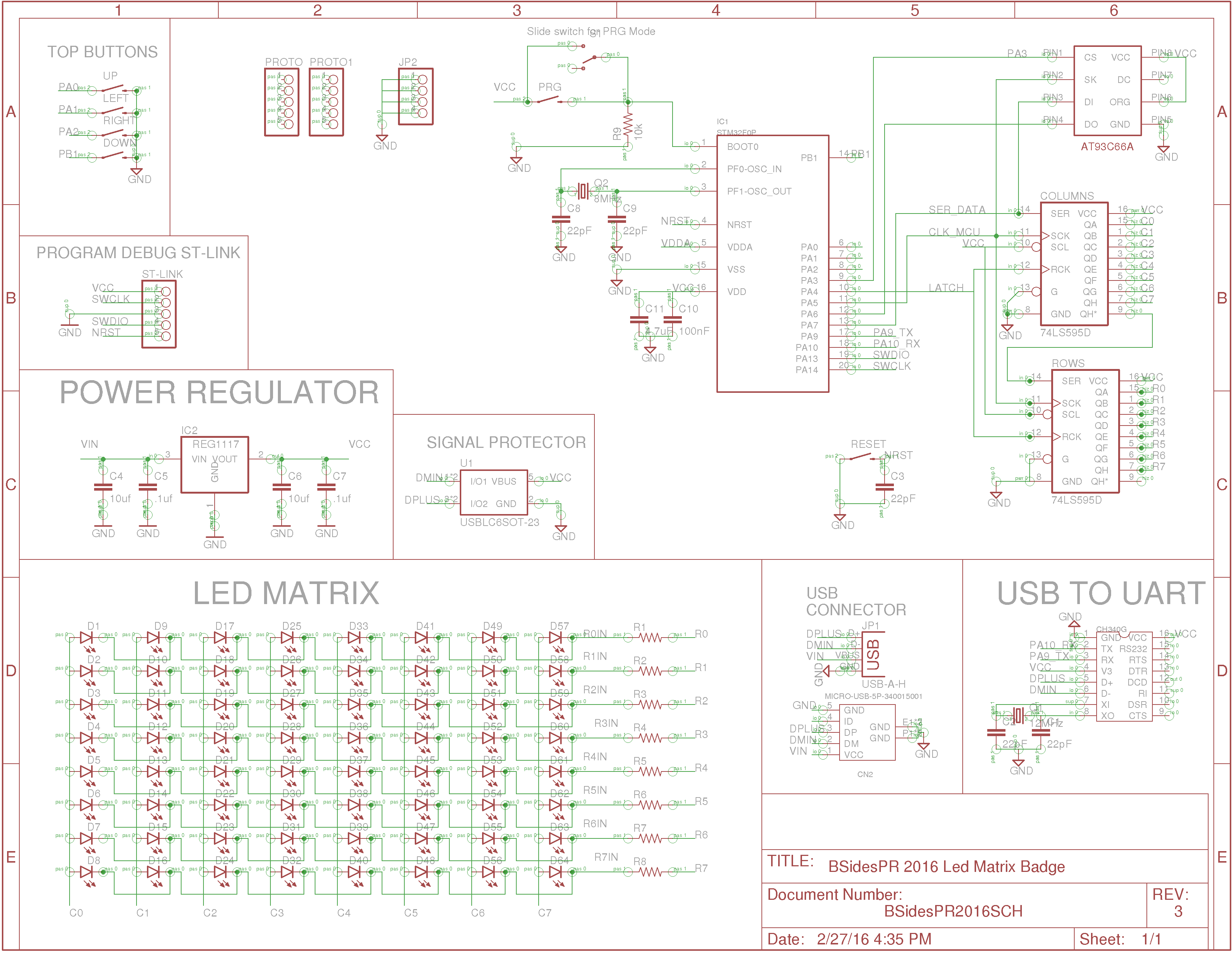
BSides PR 2016 badge? Pretty cool ahh. If you are wondering how this led matrix works, well lets look at it.
The badge led matrix is pretty simple. It consist of two shift registers that control rows and columns. Rows and Columns are represented by an eight bit number. Refer to picture bellow to show how bits are arranged in relation to the badge matrix.
When sending data from the micro controller to the badge. We first send row bits then send column bits. Data is pushed from one shift register into the other via the overflow bit. In order to turn on a led or multiple led the right combination of bits in row and column should be achieved. A 0 value on a row and a 1 value on a column will make a led to turn on.
This is an example of several leds turning on. We are using a set of functions provided in the firmware example available on
github.
This example is sending a 0x01 value to the rows ( 00000001 ) and a 0x80 to the columns ( 10000000 ). This cause the columns bits 0 - 6 to be 0 and Column bit 7 be 1. Also to have Row bits 1-7 = 0 and Row bit 1 = 0. The yellow cells with ON represent what leds shold be turned on.
To ease the sending of data a function ledMatrix.write is used. This function receives two parameters. The first parameter being the byte for the rows and the second parameter the byte for the columns. In this example the function is called ledMatrix.write( 0x01, 0x80 ).
This is a simple way of turning on several leds on the badge. Repeat same thing several times with different combination and an animation can be represented with leds.
For the very curious hackers, communication to the led matrix is via SPI and the STM32F0 supports DMA. So a clever hacker can use DMA to send data to the led matrix and free up some clock ticks from the CPU. As of this post, the example on github is not using DMA just simple serial communication.


